Peavey S-24 Bedienungsanleitung
Stöbern Sie online oder laden Sie Bedienungsanleitung nach DJ-Controller Peavey S-24 herunter. Peavey S-24 User's Manual Benutzerhandbuch
- Seite / 32
- Inhaltsverzeichnis
- LESEZEICHEN
- Mixing Console 4
- Master Functions: 9
- Setup Goal 14
- INSTALLATION 14
- Planning the installation: 15
- GROUP ASSIGN: 16
- Group mics together that 16
- Other outputs 17
- Setup Procedure: 17
- Priority/Group 19
- Faders set to -10 20
- Feedback Ferrett 20
- Monitor 1 & 2 20
- Final setup and adjustment 21
- Operation Instructions 22
- Advanced Control Setup 23
- Select Reverb Type 25
- Set Level 25
- HEADPHONE CONTROLS 26
- GLOSSARY 27
- Block Diagram 28
- SPECIFICATIONS 29
- Effective Date: July 1, 1998 31
- 80305111 32
Inhaltsverzeichnis
S-24™Mixing Console Operating GuideFor more information on other great Peavey products, go to your local Peavey dealer or online at www.peavey.com
1025. OFF-LEVEL THRESHOLD: The solo and the choir groups have adjustable threshold downward expandersthat reduce noise by lowering the signal when the
11333435they be at 0 when channel gains are set; however, they can be used tolower the overall sound level if needed.32. CONFIGURATION: The main outpu
12Input and Output Jacks:38. MIC INPUT: XLR balanced input optimized for a microphone or other low impedance source. Pin 2 is the positiveinput. Becau
1350474845. AMBIENCE MIC GAIN CONTROL: This control sets the amount of ambient sound from the room thatgoes to the Record and Remote outputs. It can
14The S-24™has an extensive and impressive list of features and functions designed to make achieving good sound forworship as easy as possible. To rea
15Planning the installation:The different inputs on the S-24™are designed for different functions. Before starting the installation, it is importantto
16The S-24™has two additional buses that allow mics to be grouped for noise reduction and compression. Try to groupmics together on adjacent inputs th
17➧ Start with a good mix on the main sound system and add only the mics that are needed to the monitors.➧ Try to keep the levels low.Other outputsRec
18i. Solo and Choir Compression controls set fullclockwise. (Master Section)j. Vocal enhance inactive (LED off)k. Turn off the Feedback Ferret by pres
19Setting Automatic mix inputs 1–4Initial Adjustment of the Automix™inputs 1–4. Each ofthese inputs will be adjusted one at a time using the sameproce
2Intended to alert the user to the presence of uninsulated “dangerous voltage” within the product’senclosure that may be of sufficient magnitude to c
20Initial Adjustment of the Monitor 1 systema. Set MON 1 and MON 2 master faders to -10.b. Set the MAIN master fader off.c. Un-mute the microphones in
21Final setup and adjustmentMost of the setup work is now complete. It is now time to make the final adjustments that will preparethe S-24 for use. W
22e. Re-adjust the channel gain control so that when the channel fader is at 0 (full up)‚ the level from the mic isloud or until a ringing sound is he
23to turn it off when they are finished. If more than one speaking mic is in use, turn the mics on and let the Automix™do the work.Inputs 1–4 are auto
24To Set:We will use choir microphones for an example. With the choir mics on and while someone isspeaking into one of the automix mics, turn the thre
25Music Style/Tempo Room Size ReverbContemporary/quick tempo Small to Medium Reverb 1Contemporary/Traditional/Medium Medium Reverb 2Traditional /Slow
26HEADPHONE CONTROLS
27GLOSSARYGain ➧ Amplification of an audio signal. A negative gain (in dB) is an attenuation or reduction of level of the signal.Ringing ➧ The resonan
28S-24™Block Diagram
S-24™ConsoleSPECIFICATIONS29IInnppuutt SSppeecciiffiiccaattiioonnssFFuunnccttiioonn MMiinn.. IInnppuutt ZZ IInnppuutt GGaaiinn SSeettttiinnggss I
3IIMMPPOORRTTAANNTT SSAAFFEETTYY IINNSSTTRRUUCCTTIIOONNSSWWAARRNNIINNGG::When using electrical products, basic cautions should always be followed, i
30HHuumm && NNooiisseeOOuuttppuutt RReessiidduuaall NNooiissee SS//NN RRaattiioo ((RReeff.. ++44 ddBBuu)) TTeesstt CCoonnddiittiioonns
31PEAVEY ELECTRONICS CORPORATION LIMITED WARRANTYEffective Date: July 1, 1998WWhhaatt TThhiiss WWaarrrraannttyy CCoovveerrssYour Peavey Warranty co
Features and specifications subject to change without notice.Peavey Electronics Corporation • 711 A Street • Meridian • MS • 39301 (601) 483-5365 • F
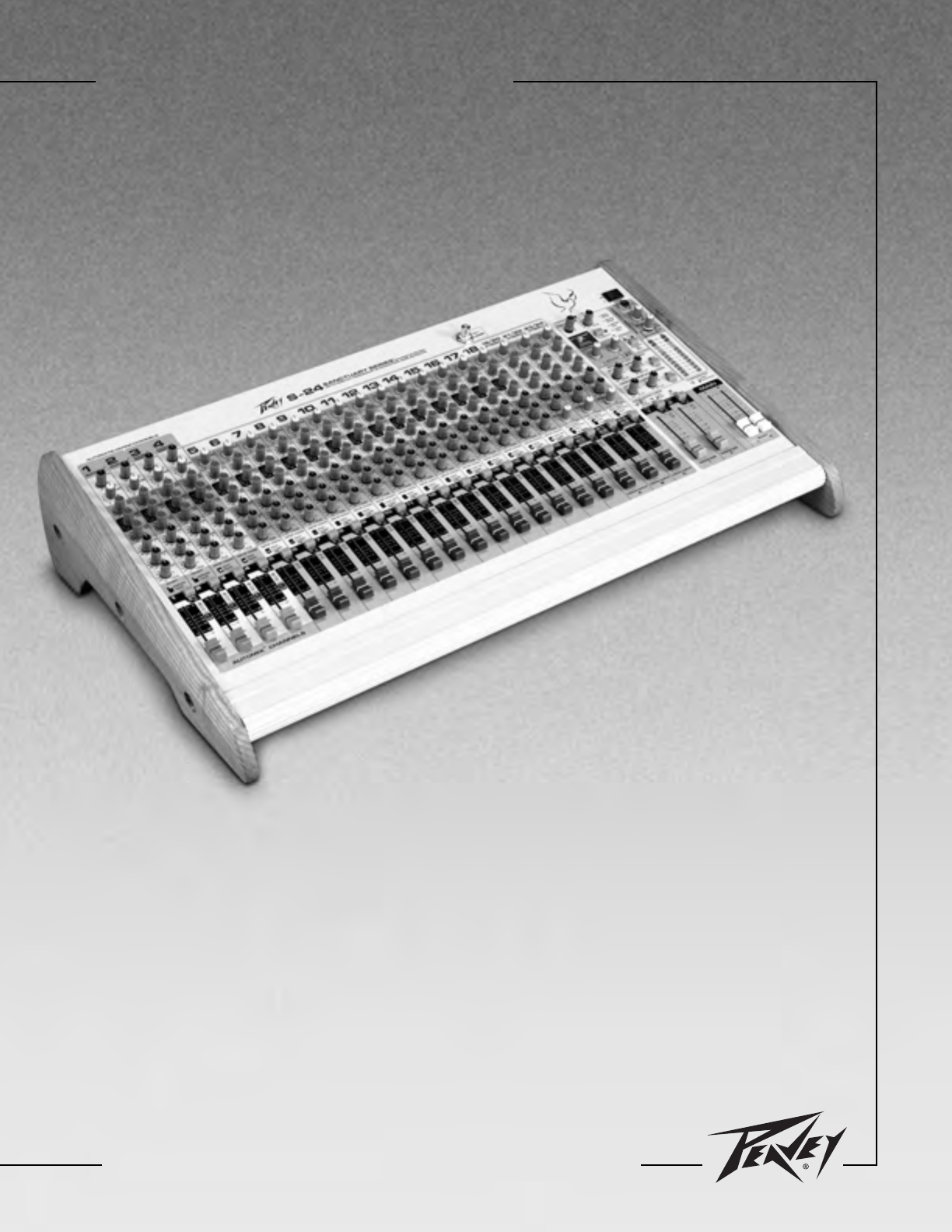
4S-24™Mixing ConsoleDescriptionThe S-24 Sanctuary Series is a 21 channel mixing console specifically designed to meet the needs of churches, schools a
5CHANNEL & MASTER FUNCTIONSThe headphone amplifier with headphone/meter selector switch is another important tool for setting and operating the S-
61. COMPRESSOR THRESHOLD: The first four channels have auto-mixing and compressor capabilities whenassigned to the pulpit or wireless group. These sof
7676. MONITOR SEND (1–2): The monitor sends adjust the level of the channel signal added to the monitor mix. Forthe Automix channels 1-4, the monitor
811. FADER: This is the channel output-level control. This control works somewhat differently on the Automix™channels 1–4 and the remaining inputs. On
9Master Functions:17. PHANTOM POWER: Applies +48 VDC voltage to the input XLR connectors to power microphonesrequiring it. If phantom power is used, d
© 2020, manymanuals.de. Alle Rechte vorbehalten. | 2.128 s |
 Manymanuals.com
 Manymanuals.de
 Manymanuals.fr
 Manymanuals.it
 Manymanuals.pl
 Manymanuals.cz
 Manymanuals.es
 Manymanuals-pt.com
Kommentare zu diesen Handbüchern